Solution topic
Capless Induction Sealing: Bench Stations, 1–8 Head Lines and Seal Checks
Induction-seal foil to bottle mouths before fitting an outer cap. The series supports project-specific configurations with 1–8 sealing heads; current footage shows six heads. Selec
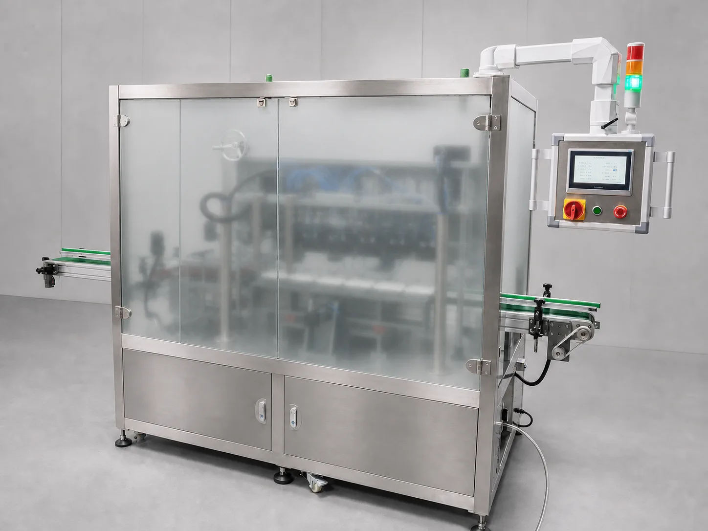
1–8 Head Capless Induction Foil Sealing Line: Six-Head Machine Demo
First-party video of the current six-head machine showing inline conveying, locating carriers and six sealing heads. The series is configurable with 1–8 heads; video duration is not an output claim.
- Induction-seal foil to bottle mouths before fitting an outer cap. The series supports project-specific configurations with 1–8 sealing heads; current footage shows six heads. Select head count from bottle and foil samples, positioning and line cycle, then check outer-cap fit after sealing.
Solution summary prepared for you
- Which capless induction foil sealer fits manual batches versus inline production: YJ-IF110 or YJ-IF610?
- What are the differences in applicable boundaries between IF110 and IF610?
- Can thermal imaging screen for missing foil and low heat after induction sealing?
Route comparison
- Projects that need to establish a process window with real bottle samples and mainly use manual bottle placement and removal on site.
- IF110's benchtop horizontal-shift structure makes it easy to confirm positioning, shifting, and induction sealing in one independent station.
- IF110 is configured as an independent benchtop station; automatic loading/unloading, inspection, and line integration need separate confirmation.
- When the project clearly requires continuous conveying, multi-position synchronization, and complete upstream/downstream interlocks, the entire line should not be estimated based only on a benchtop station.
- Focus on evaluating YJ-IF110 and conduct trial runs with actual containers, foil, and fixtures.
- Projects with stable bottle shapes, wanting linear conveying and multi-position locating carriers, and ready to define full line cycle time.
- IF610's six parallel sealing heads and linear carrier structure are suitable for further discussion of multi-position sealing and upstream/downstream integration.
- Single-cycle meaning, actual capacity, loading release logic, interlocks, and conveying interfaces have no universal fixed values.
- When bottle shape is not finalized, foil assembly is still changing frequently, or only small trial production is needed on site, it is not advisable to freeze the six-head configuration.
- Focus on evaluating YJ-IF610 and conduct cycle acceptance with a complete line and representative samples.
- Projects that want to establish online screening for defects such as missing foil, reversed foil, missing edge, damage, wrinkles, overheating, low heat, tilted caps, loose caps, or false seals.
- FI310 can complete thermal image acquisition, feature analysis, result recording, and alarm or rejection signal linkage according to the project.
- Thermal images are process and defect screening evidence and cannot directly replace leak, peel, or seal strength tests.
- When there are no representative good and defective samples and no actual line speed and thermal environment data, inspection speed and accuracy should be determined after on-site blind testing.
- Evaluate YJ-FI310 downstream of the induction sealing equipment and determine acceptance boundaries based on blind test results.
Associated Equipment / Consumables
1–8 Head Inline Capless Induction Foil Sealing LineInduction-seal foil to bottle mouths before fitting an outer cap. The series supports project-specific configurations with 1–8 sealing heads; current footage shows six heads. Select head count from bottle and foil sam...
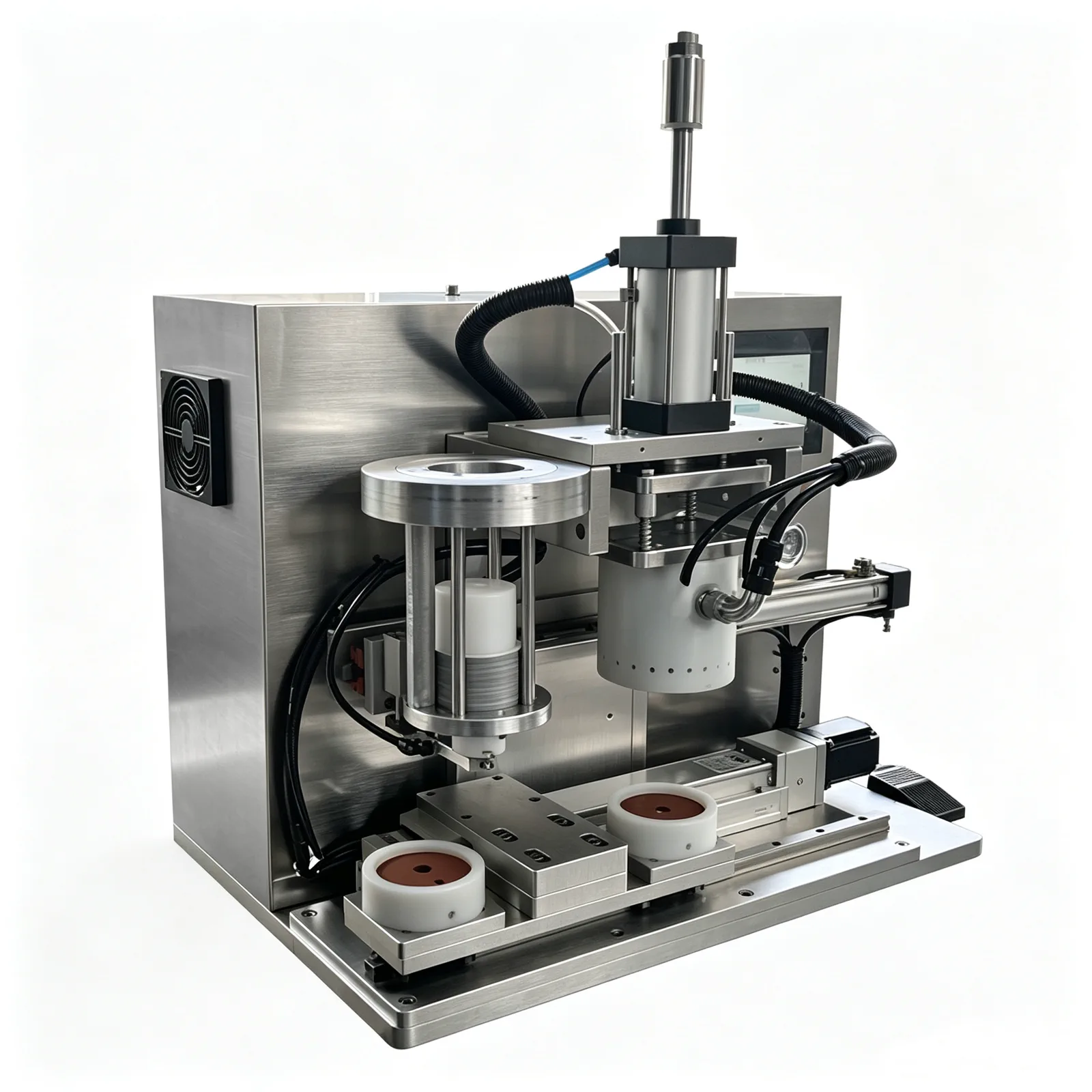 Benchtop Horizontal-Shift Capless Induction Foil Sealer
Step 1: Confirm container and foil assembly; First use actual samples to confirm whether the bottle mouth and foil assembly provide a basis for repeatable testi...
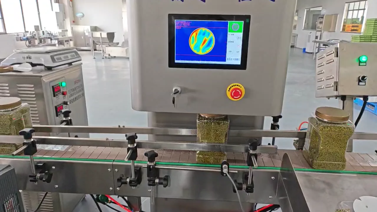 Inline Thermal-Imaging Foil-Seal Integrity Inspection Machine
Step 1: Confirm container and foil assembly; First use actual samples to confirm whether the bottle mouth and foil assembly provide a basis for repeatable...
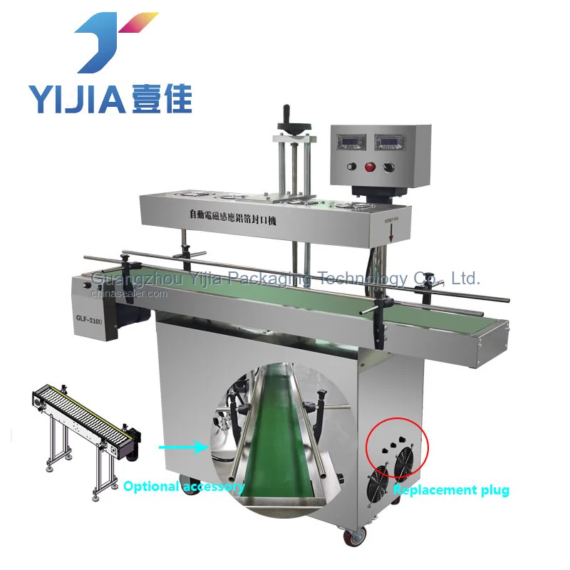 Inline Induction Foil Sealer
Step 1: Confirm container and foil assembly; First use actual samples to confirm whether the bottle mouth and foil assembly provide a basis for repeatable testing; Leak-proof caps, inner...
Core process
Sample details
Actual container with close-up photos of the mouth and complete dimensions can first verify locating method, fixture boundaries, and subsequent sample needs.
Provide actual container, bottle mouth photos, mouth diameter, outer profile, and height.Confirm that the bottle mouth has no outer cap during sealing, so that equipment boundaries can be defined based on independent foil placement, bottle positioning, and induction station.
Indicate whether the sealing is confirmed to be without an outer cap.The composite structure and supply state of the foil assembly need to be checked together with the bottle material to arrange sealing trials rather than selecting a machine only by mouth diameter.
Provide foil assembly material, thickness, composite structure, and supply method.Hourly capacity, number of operators, and conveying method together determine whether to use a benchtop shift station or evaluate a continuous multi-head line.
Indicate target hourly capacity, number of operators, and whether continuous conveying is required.Upstream/downstream interfaces, conveying reference, and available space are used to verify line integration, operation and maintenance positions, and necessary safety protection.
Provide upstream/downstream equipment, conveying height, site layout, and safety requirements.First agree on how the seal itself will be accepted, then separately define thermal imaging screening targets to avoid equating temperature anomalies with leakage or strength conclusions.
Agree on acceptance methods for seal appearance, peel, leakage, and thermal imaging screening.Common selection mistakes
View detailed technical notes
How can foil be sealed before fitting an outer cap?
First confirm the bottle mouth, foil assembly and contact/positioning conditions, then choose a standalone bench station or an inline configuration with 1–8 heads. Current multi-head footage shows six heads; the series is not limited to six. Any post-seal screening method must be validated with representative good and defective samples, not inferred from a video.
First determine the packaging route
For cap-less bottle mouth projects, first confirm the induction sealing window with containers and foil assemblies, then choose the IF110 benchtop horizontal-shift machine or the IF610 six-head linear line based on loading/unloading method. If online screening is needed, evaluate the FI310 thermal imaging solution downstream.
Manual loading/unloading and benchtop shifting
Suitable for: projects that need to establish a process window with real bottle samples and mainly use manual bottle placement and removal on site. Advantages: IF110's benchtop horizontal-shift structure makes it easy to confirm positioning, shifting, and induction sealing in one independent station. Limitations: IF110 is configured as an independent benchtop station; automatic loading/unloading, inspection, and line integration need separate confirmation. Not recommended: when the project clearly requires continuous conveying, multi-position synchronization, and complete upstream/downstream interlocks, the entire line should not be estimated based only on a benchtop station. Equipment direction: focus on evaluating YJ-IF110 and conduct trial runs with actual containers, foil, and fixtures.
Match 1–8 heads to the complete line cycle
For projects with reasonably stable bottle and foil specifications that need conveying and multi-position handling. Select head count from bottle pitch, carriers, per-container process time and adjacent-line cycles; more heads do not guarantee a proportional output increase. Specify whether infeed, foil placement, capping, inspection and rejection are included. Confirm output over continuous complete cycles and check outer-cap fit after sealing.
Thermal screening does not replace seal-integrity testing
After stabilizing sealing, assess thermal image capture, anomaly screening, records and alarm or rejection interfaces. Confirm detectable defects, missed detections and false rejects using labelled samples and blind tests at the actual line speed and thermal conditions. A low or absent thermal signal alone does not establish that foil is missing. Leakage, peel and seal-strength acceptance require their own agreed tests.
Recommended equipment route: Step 1: Confirm the container and aluminum foil assembly
First use actual samples to confirm whether the bottle mouth and aluminum foil assembly provide a repeatable test basis.
Recommended equipment route: Step 2: First rule out the conventional inline route with caps
If the container can provide pressing conditions by screwing on an outer cap, first compare conventional inline solutions. Projects without an outer cap then proceed to IF110 or IF610.
Recommended equipment route: Step 3A: Benchtop station trial production
Manual loading/unloading projects can first confirm fixture positioning and the induction sealing window at a standalone station.
Recommended equipment route: Step 3B: Six-head line evaluation
Continuous production projects need to confirm multi-station carriers, conveying cycle time, and front/rear interlocking as a complete line.
Recommended equipment route: Step 4: Post-stage anomaly screening
After the sealing process is stable, use representative defect samples to establish thermal imaging screening and alarm or rejection boundaries.
Common questions
Can induction foil sealing be done without an outer cap?
The IF110 or IF610 can be evaluated, but actual samples of the container, bottle mouth, and foil assembly must be provided for confirmation.
Which model is better for small batches?
For small-batch projects mainly using manual loading and unloading, the IF110 independent benchtop station can be prioritized for evaluation.
Is a six-head line necessarily faster than a benchtop machine?
Judgment cannot be based only on the number of sealing heads; actual cycle time depends on carriers, conveying, release logic, and full-cycle testing.
What defects can FI310 screen?
FI310 can be used to screen for defects such as missing foil, reversed foil, missing edge, damage, wrinkles, overheating, low heat, tilted caps, loose caps, and false seals.
Can thermal imaging directly determine leakage?
No, thermal images are process screening evidence; leakage conclusions still require corresponding verification methods.
Can the three machines be purchased separately?
They can be sold separately; whether to combine and the interface scope should be confirmed based on project goals and acceptance requirements.