Solution topic
What Can Thermal Imaging Reveal After Induction Foil Sealing? The Correct Scope of Aluminum Foil Integrity Screening
See what YJ-FI310 thermal imaging can screen after foil sealing, how to run blind tests, and why leak and seal-strength tests remain separate.
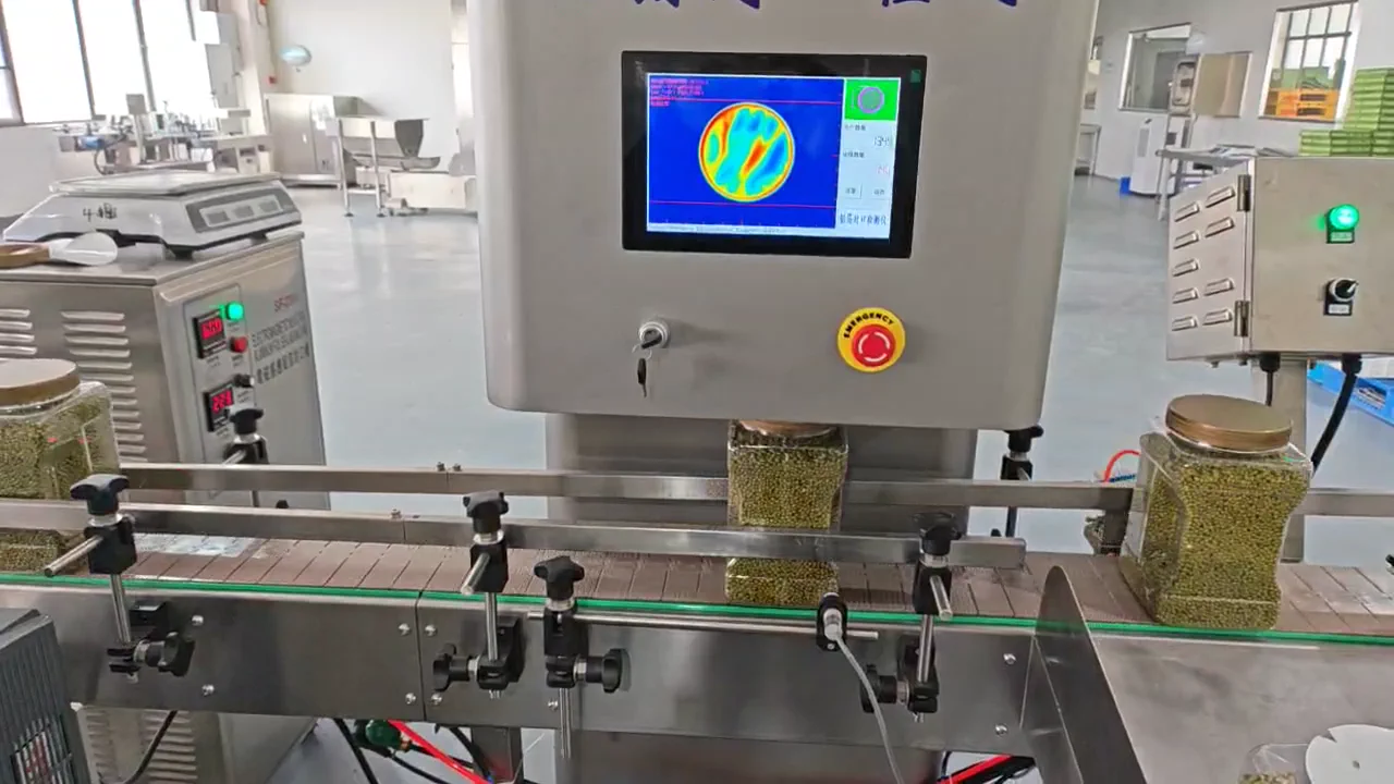
- The FI310 captures thermal images after induction foil sealing on bottle mouths, screens for agreed anomalies through feature analysis, and can output recording, alarm, or rejection signals as per project requirements. It is a process screening tool, not a substitute for leak rate or seal strength testing.
Solution summary prepared for you
- What can thermal imaging detect after induction foil sealing, and what still requires leak or seal-strength testing?
- Can thermal imaging prove the bottle mouth is absolutely leak-free?
- How to confirm FI310 detection speed and accuracy?
Route comparison
- Projects in the process development stage that need to first establish good product, defect samples, and acceptance methods.
- Facilitates comparing leak, peel, appearance, and thermal image results one by one to establish explainable screening boundaries.
- Offline sampling cannot represent that every product is inspected, nor prove trigger stability at full line speed.
- When per-bottle online screening and automatic rejection are clearly required, manual sampling alone cannot be relied upon.
- First complete sample library and blind test design, then proceed to FI310 online configuration.
- Projects with relatively stable induction sealing processes that want to observe heat distribution per bottle and screen agreed anomalies.
- FI310 can perform thermal image capture, feature analysis, anomaly judgment, and result recording.
- Detection performance depends on bottle type, aluminum foil, actual line speed, bottle spacing, shading, and on-site thermal environment.
- When the upstream sealing process continuously drifts, or there are no representative defect samples, accuracy should be determined in blind tests after process stabilization.
- Place YJ-FI310 after the sealing section and complete blind tests under actual production conditions.
- Projects concerned with both heat distribution and visible cap position, appearance defects, or other visual items.
- Thermal imaging and visible light vision can cover different evidence separately, then define alarms or rejection according to the project.
- Combined equipment does not automatically expand acceptance scope; each defect type needs samples and judgment criteria.
- When the customer only needs single thermal anomaly screening, unrelated inspections should not be added just to increase equipment count.
- FI310 handles thermal images; sealing vision or tilted/missing cap equipment is only an independent option.
Associated Equipment / Consumables
Inline Thermal-Imaging Foil-Seal Integrity Inspection MachineThermal imaging screens for missing, reversed, damaged, wrinkled or thermally abnormal foil seals and cap-position anomalies. It does not prove absolute leak rate or seal strength; performance requires representative...
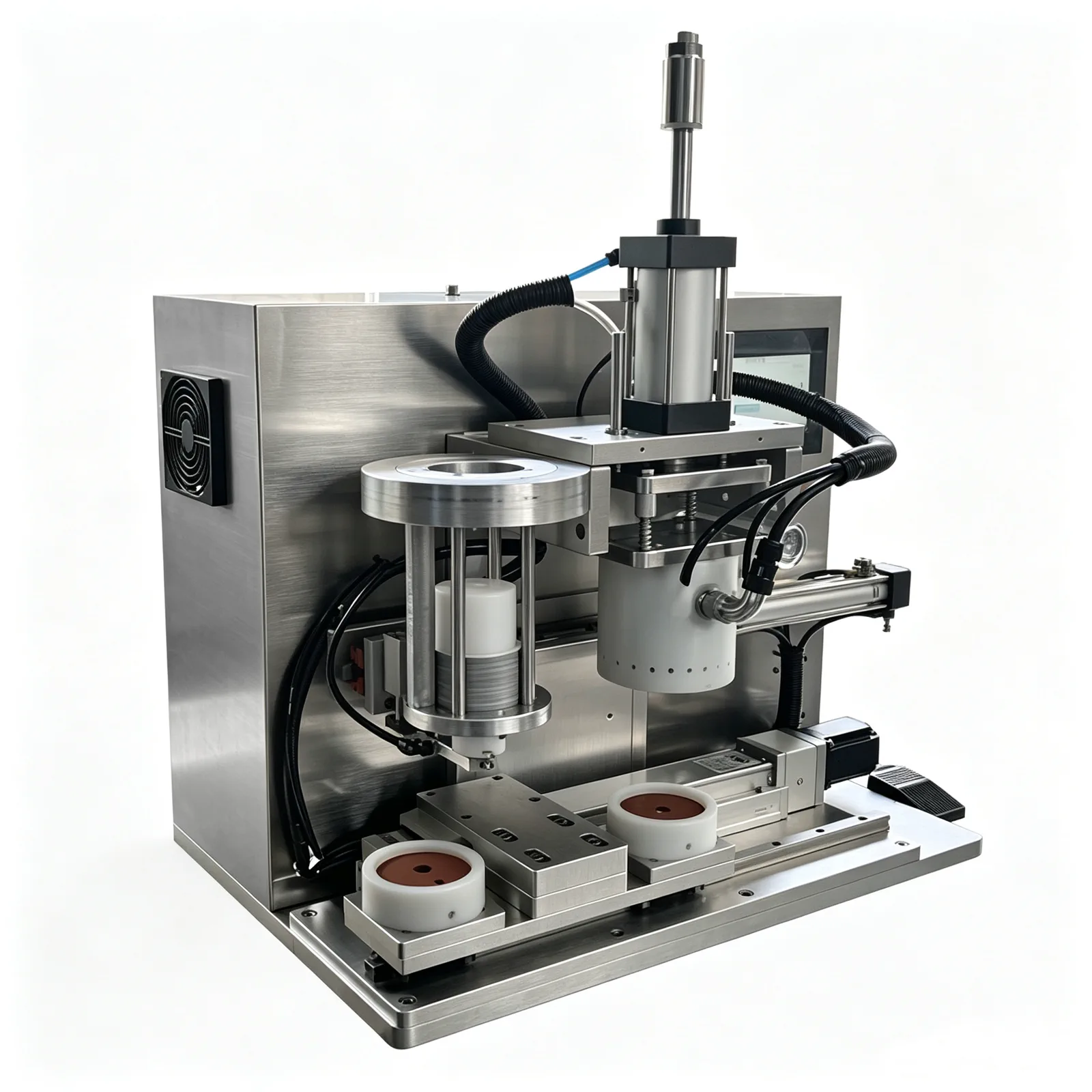 Benchtop Horizontal-Shift Capless Induction Foil Sealer
Step 1: Stabilize upstream sealing baseline; First let the upstream section form repeatable normal sealing samples on representative containers and aluminum foi...
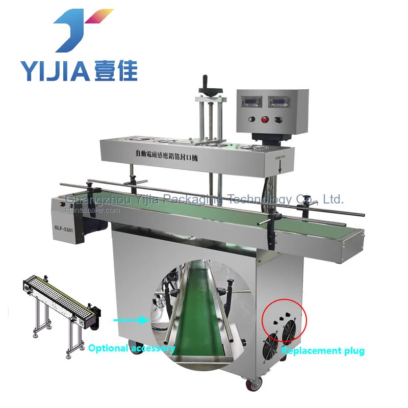 Inline Induction Foil Sealer
Step 1: Stabilize upstream sealing baseline; First let the upstream section form repeatable normal sealing samples on representative containers and aluminum foil; YJ-IF110, YJ-IF610, or o...
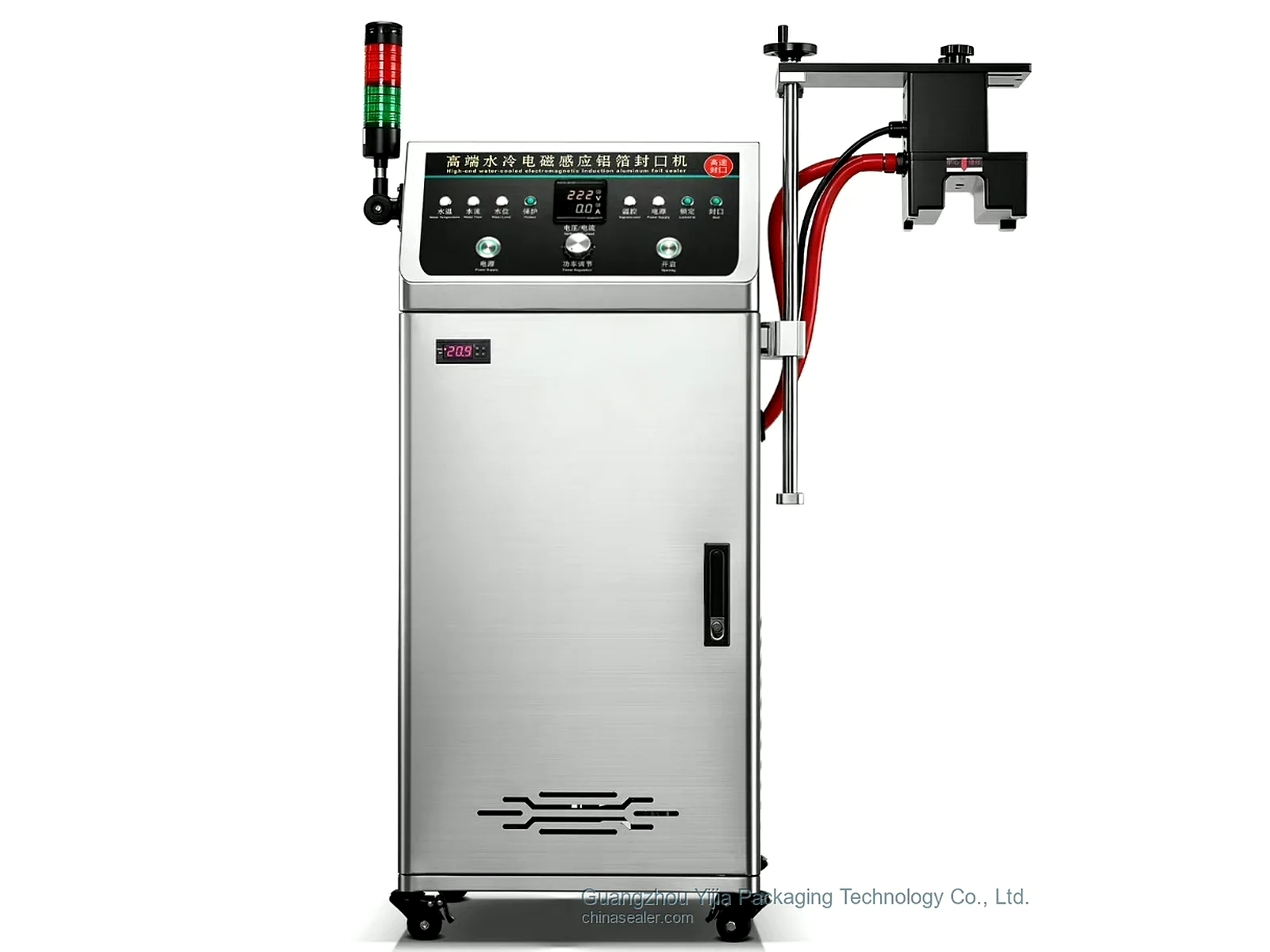 Inline Induction Foil Sealing Machine
Step 1: Stabilize upstream sealing baseline; First let the upstream section form repeatable normal sealing samples on representative containers and aluminum foil; YJ-IF110, YJ-IF...
Core process
Sample details
Representative good products and normal sealing samples are used to collect stable heat distribution; actual production conditions must still be recorded before establishing the screening baseline.
Provide representative good bottles and normal sealing samplesMissing foil, reversed foil, missing edge, damage, and wrinkles need to be retained separately to confirm which defects can form repeatable thermal features.
Provide defect samples such as missing foil, reversed foil, missing edge, damage, and wrinklesOverheating, low heat, tilted cap, loose cap, and false seal should be made into comparison samples by category according to the project, and their generation method and review results recorded.
Provide samples for overheating, low heat, tilted cap, loose cap, and false seal itemsBottle type, bottle mouth, cap components, and aluminum foil dimensions are used to determine imaging area and occlusion boundaries; different structures should be sampled and verified separately.
Provide dimensions of bottle type, bottle mouth, cap components, and aluminum foil structureActual line speed, bottle spacing, content temperature, and environmental heat sources change the observation window; baseline should be collected according to the production site.
Explain actual line speed, bottle spacing, content temperature, and on-site thermal environmentAlarm, rejection, recording, and FAT/SAT acceptance criteria must be clearly written separately; thermal imaging screening results also require agreed review methods.
Define alarm, rejection, recording, and acceptance requirements for FAT and SATCommon selection mistakes
View detailed technical notes
Real customer problem
Our induction sealing line occasionally has missing foil, low heat, wrinkles, or abnormal cap positions. We hope to detect online and alarm or reject. What issues can thermal imaging cover, how should good and defective samples be prepared, and what sealing conclusions cannot be directly given by thermal images?
First determine the packaging route
FI310 captures thermal images after bottle mouth aluminum foil sealing, screens agreed anomalies through feature analysis, and can output records, alarms, or rejection signals according to the project. It is a process screening tool, not a substitute for leak rate or seal strength testing.
Manual sampling and offline verification
Suitable for: projects in the process development stage that need to first establish good product, defect samples, and acceptance methods. Advantages: facilitates comparing leak, peel, appearance, and thermal image results one by one to establish explainable screening boundaries. Limitations: offline sampling cannot represent that every product is inspected, nor prove trigger stability at full line speed. Not recommended: when per-bottle online screening and automatic rejection are clearly required, manual sampling alone cannot be relied upon. Equipment direction: first complete sample library and blind test design, then proceed to FI310 online configuration.
Online thermal imaging process screening
Suitable for: projects with relatively stable induction sealing processes that want to observe heat distribution per bottle and screen agreed anomalies. Advantages: FI310 can perform thermal image capture, feature analysis, anomaly judgment, and result recording. Limitations: detection performance depends on bottle type, aluminum foil, actual line speed, bottle spacing, shading, and on-site thermal environment. Not recommended: when the upstream sealing process continuously drifts, or there are no representative defect samples, accuracy should be determined in blind tests after process stabilization. Equipment direction: place YJ-FI310 after the sealing section and complete blind tests under actual production conditions.
Visible appearance vision combined with thermal imaging
Suitable for: projects concerned with both heat distribution and visible cap position, appearance defects, or other visual items. Advantages: thermal imaging and visible light vision can cover different evidence separately, then define alarms or rejection according to the project. Limitations: combined equipment does not automatically expand acceptance scope; each defect type needs samples and judgment criteria. Not recommended: when the customer only needs single thermal anomaly screening, unrelated inspections should not be added just to increase equipment count. Equipment direction: FI310 handles thermal images; sealing vision or tilted/missing cap equipment is only an independent option.
Recommended equipment route: Step 1: Stabilize upstream sealing baseline
First let the upstream section form repeatable normal sealing samples on representative containers and aluminum foil.
Recommended equipment route: Step 2: Build good and defect sample library
Use real good products and agreed defect samples to determine thermal image features and acceptable screening boundaries.
Recommended Equipment Route: Step 3: Inline Thermal Imaging Assessment
Verify trigger, imaging, and result recording at full line speed, actual bottle spacing, and on-site thermal environment.
Recommended Equipment Route: Step 4: Alarm, Rejection, and Traceability Interfaces
Configure alarm, rejection, or recording interfaces according to the confirmed anomaly categories and production line logic.
Common questions
Is the FI310 an ordinary visible light camera?
It uses thermal imaging capture and feature analysis as its core; visible light inspection is a separately evaluated project option.
Can it be adjusted first without defect samples?
You can first observe good products, but this cannot confirm the screening capability and accuracy for various defects.
Can the equipment directly control rejection?
Alarm or rejection signals can be output according to the project, but the actual interface and handling logic must be confirmed with the production line.
Can different bottle types share one set of parameters?
It depends on the bottle mouth, cap components, aluminum foil structure, and thermal background; changing models usually requires reconfirming the field of view and judgment conditions.
Can thermal imaging replace leak testing?
No, it is suitable for online screening; leakage or seal strength still requires corresponding verification methods.
How to accept the FI310?
Use representative good and defective samples, conduct blind tests at actual line speed and environment, and statistically process and handle results as agreed.