Solution topic
Air-Cooled, Water-Cooled, Inline Induction Foil Sealing and Paper Can Press Capping Routes
Compare air-cooled, water-cooled and inline induction foil sealers by liner, container, duty cycle and layout. Capless routes are reviewed separately.
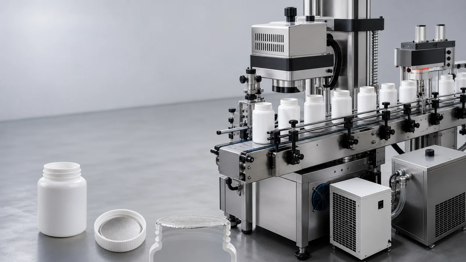
Continuous bottle-line induction sealing video
Video confirms inline transport and head structure; it does not establish speed or seal acceptance.
- The bottle mouth, cap, and aluminum foil liner first determine whether induction sealing is possible. Air-cooled, water-cooled, or inline equipment should be selected based on mouth diameter, continuous operation, and on-site maintenance conditions; paper can and pail press capping is a separate specialized branch.
Solution summary prepared for you
- How do you choose between air-cooled, water-cooled and inline induction foil sealing equipment?
- The cap unscrambling and feeding system and automatic screw capper handle cap closure; the induction sealing head handles the cap liner inner seal; the paper can/plastic pail aluminum foil film sealing and cap pressing machine handles fi...
- Official bottles, caps, liners, container mouth dimensions, operation schedule, and on-site conveying information are necessary inputs for determining cooling structure and line integration interface.
Route comparison
- Suitable for projects that first verify the cap liner combination, or where the production schedule allows benchtop, single-machine inner sealing.
- Benchtop air-cooled induction foil sealing machines facilitate single-machine trial sealing with formal bottle caps and liners, and on-site maintenance conditions are relatively straightforward.
- Whether it meets operational requirements still depends on mouth diameter, liner, environment, and continuous work schedule; it cannot be inferred from the 'air-cooled' name.
- If trial sealing shows unsuitable heat dissipation or continuous operation conditions, or if the project must directly integrate into a stable bottle line, compare other structures.
- For conventional single machines or samples, first evaluate a benchtop air-cooled induction foil sealing machine and record continuous sample performance.
- Applicable to packaging lines where, after sample and operational evaluation, the water-cooled structure is confirmed to better match continuous production and on-site maintenance.
- Water-cooled induction foil sealing machines offer another heat dissipation structure and can be project-tested for continuous operation, large diameters, and other conditions.
- The site needs a suitable water-cooling circuit, installation space, and maintenance arrangements; sealing results are still confirmed by formal samples.
- If the site is inconvenient for water-cooling setup or maintenance, and benchtop air-cooled already meets verified production requirements, no mechanical upgrade is needed.
- When actual operation places higher demands on heat dissipation, evaluate water-cooled induction foil sealing machines and their maintenance conditions.
- Suitable for projects with stable filling, cap supply, screw capping, and conveying processes that require continuous induction inner sealing after capping.
- Inline induction foil sealing machines can continuously connect with automatic screw cappers and conveying stations, reducing secondary handling of bottles.
- Bottle posture, bottle spacing, sealing head height, and upstream/downstream machine control all affect the pass-through process; all bottle types require inline verification.
- If the cap liner is not finalized, or existing conveying frequently jams and bottles tip over, do not fix inline sealing parameters prematurely.
- For stable bottle lines, use an inline induction foil sealing machine and coordinate the automatic screw capper and conveying spacing.
- Suitable for paper cans or plastic pails that use a separate liner for sealing and require continued external cap pressing.
- Paper can/plastic pail foil sealing and press capping machines match dedicated liner sealing and press capping paths to the can/pail mouth structure.
- The can mouth flatness, liner layers, container pressure resistance, and external cap depth all need sampling; do not reuse ordinary bottle cap liner parameters.
- If the container actually uses a cap liner for induction sealing, return to the screw capping plus induction inner sealing route; do not mix in direct sheet film heat sealing machines.
- For separate liner plus external cap, choose a paper can/plastic pail foil sealing and press capping machine; for wide-mouth heat sealing, compare pail equipment.
Associated Equipment / Consumables
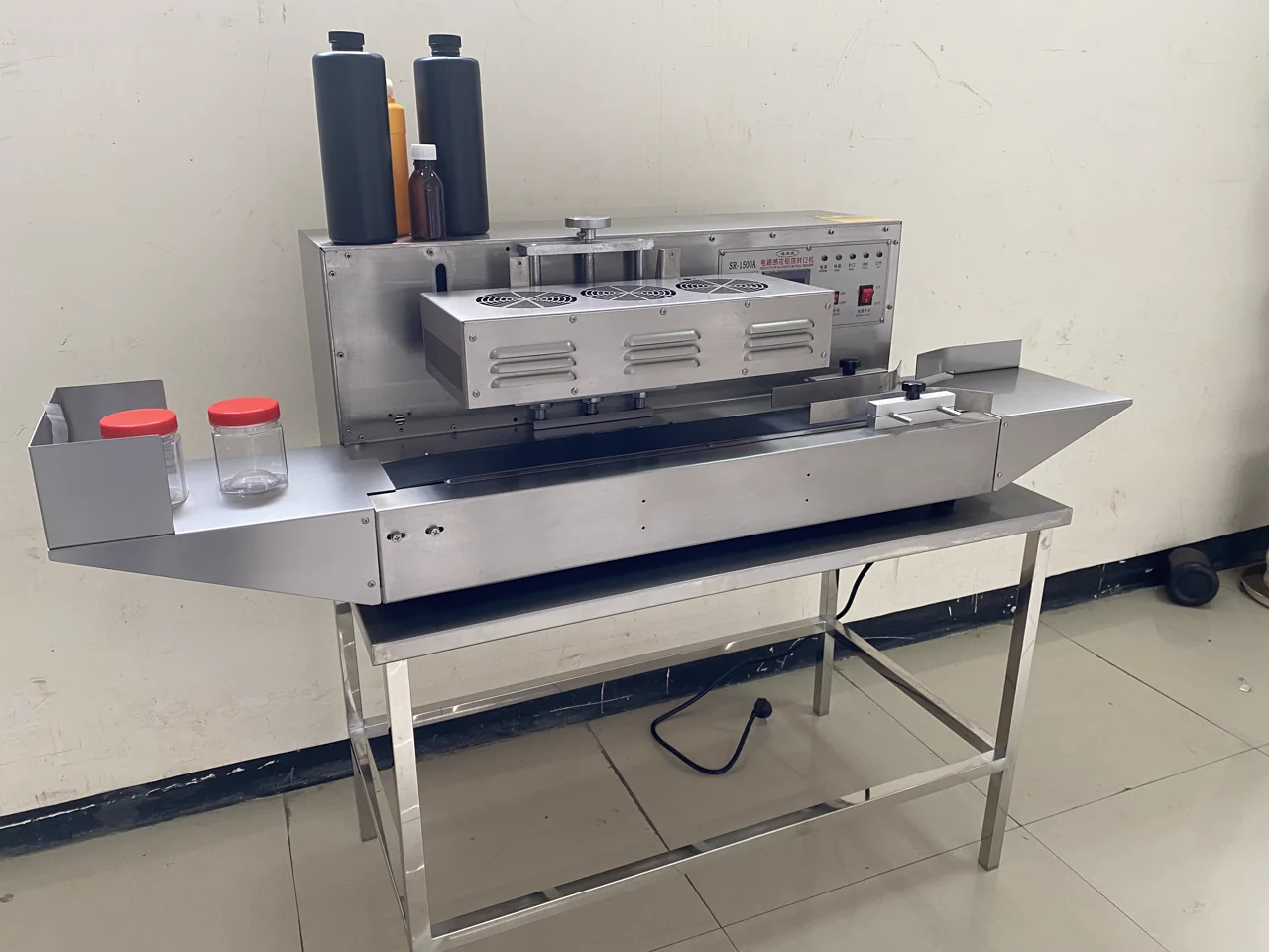 Benchtop Air-Cooled Induction Foil Sealer
This benchtop unit creates an induction inner seal after a cap correctly compresses a compatible foil liner. It is not a capless direct-lidding heat sealer and cannot seal ordinary foil without the required induction...
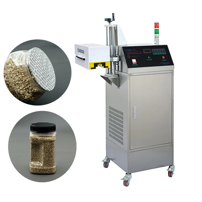 Water-Cooled Inline Induction Cap Sealer
For continuous inner sealing after capping; validate liners, head match, pitch, thermal duty, cooling, and intended shift.
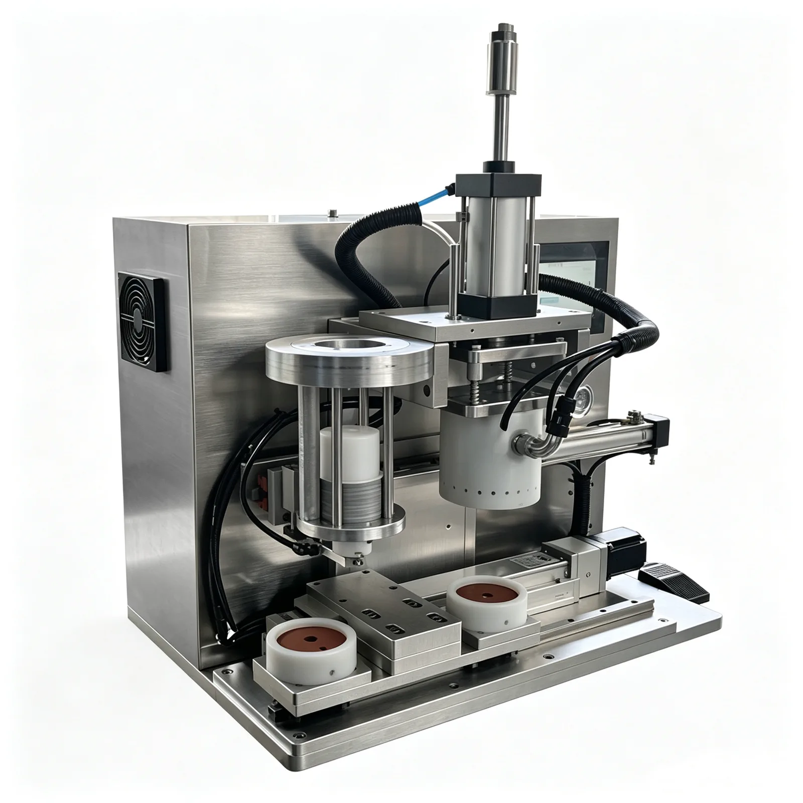 Benchtop Horizontal-Shift Capless Induction Foil Sealer
Compare this sample-led capless route separately from standard capped bottle induction sealing.
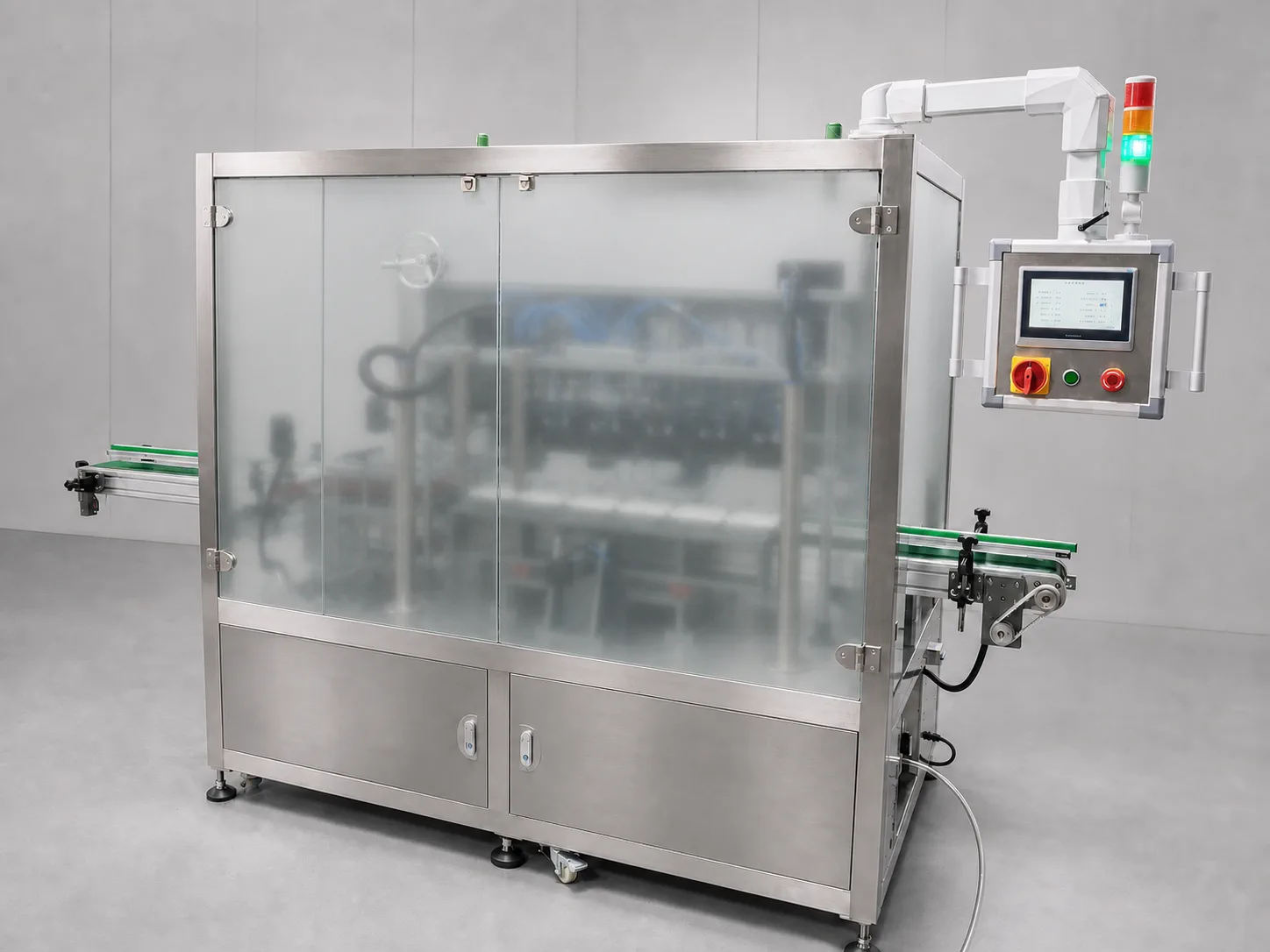 1–8 Head Inline Capless Induction Foil Sealing Line
Core process
The container mouth, cap, and aluminum foil liner must be trial sealed as a set; first confirm the heat seal layer, placement direction, and rim contact.
For continuous bottle lines, a cap unscrambling and feeding system can organize caps, and an automatic screw capper completes the appropriate capping action.
Use official samples to compare benchtop air-cooled, water-cooled, and inline induction equipment, and choose based on mouth diameter, operation schedule, and maintenance conditions.
When connecting an inline induction aluminum foil sealing machine to an existing production line, verify bottle spacing, guiding, bottle height variation, and sealing head position.
If paper cans or plastic pails use a separate film disc plus outer cap, switch to a paper can/plastic pail aluminum foil film sealing and cap pressing machine for verification.
For small containers such as reagent tubes, use corresponding aluminum foil sealing equipment for sampling, and record inner seal, opening, and appearance results after sealing.
Sample details
Photograph and send samples of the container, cap, and liner as a set, clearly marking liner layers, placement direction, and bottle mouth contact surface.
Official bottles or jars, bottle mouth dimensions, cap inner and outer structure, aluminum foil liners, and post-sealing target samples.Indicate whether the container is plastic, glass, paper can, or pail, and supplement the content state and whether the rim is prone to contamination.
Container material, rim flatness, content type, post-filling mouth condition, and all changeover specifications.Operation schedule includes normal production duration, start-stop frequency, and changeovers; do not use vague high-speed or low-speed labels instead.
Planned output, shifts, continuous operation mode, bottle spacing, and changeover frequency for different specifications.The liner must be stably held by the cap before entering the induction station; cap unscrambling, placement, and tightening methods need to be tested together with the inner seal.
Cap supply method, cap type list, automatic screw capper status, post-capping samples, and opening experience requirements.For existing line modification, provide site, conveying direction, bottle height variation, and control interface. For paper can or heat sealing projects, additionally provide film disc and outer cap information.
Workshop drawing, conveyor dimensions, upstream and downstream machine information, power and maintenance conditions, special containers, and film and cap samples.Common selection mistakes
Containers with the same mouth diameter may require different sealing configurations if the cap type, liner layers, or operation schedule differ; do not only report the bottle mouth diameter.
If the liner's heat seal layer faces the wrong direction or does not match the bottle mouth material, even if the surface appears to have aluminum foil, it cannot represent a reliable inner seal.
If the cap does not hold the liner stably against the rim, subsequent adjustment of induction conditions cannot compensate for fluctuations in the closed cap state.
Air cooling or water cooling should be compared based on actual continuous operation and maintenance environment; directly selecting a machine by a generalized speed label can easily overlook heat dissipation and site conditions.
After replacing with official caps and liners, the fit and sealing conditions may change together; early temporary samples cannot be used as the basis for final acceptance.
View detailed technical notes
First confirm the cap liner structure
Conventional capped bottle lines rely on the liner inside the cap to sit close to the container mouth after screw capping, and then the induction equipment completes the inner seal. Sealing without an external cap is a different packaging material and equipment path, and should be verified separately with the corresponding container and foil liner.
Stabilize the closed-cap state before induction sealing
The cap unscrambling and feeding system handles cap sorting and supply, and the automatic screw capper adapts to the cap type for closing. Only when the liner position, fit, and bottle mouth cleanliness are stable after capping can subsequent induction sealing machines be compared.
Cooling structure is selected by trial sealing and operation
The choice between benchtop air-cooled and water-cooled induction foil sealing machines should consider the bottle mouth, liner, actual operation, and on-site maintenance conditions. Do not copy fixed speed ranges; let the same batch of formal samples undergo corresponding working-condition tests.
Inline machines should be accepted together with conveying
Inline induction foil sealing machines are suitable for integration into stable bottle lines. When linked, besides the sealing result, observe the bottle spacing after automatic screw capping, conveying guides, bottle height variations, and container position during start/stop.
Paper can liner and bottle cap liner processes differ
If paper cans or plastic pails use a separate aluminum foil liner and continue with an external cap, use a paper can/plastic pail foil sealing and press capping machine. Large-diameter pail heat sealing machines and bottle inline heat sealing machines belong to the heat sealing branch and should not be confused with cap liner induction sealing.
Set up separate sample groups for special containers
Reagent tube foil sealing machines serve corresponding small tube mouths, while ordinary induction foil sealing machines can be used for compatible bottles, cans, and pails. When containers vary in specification or process, keep samples in groups and record seal edge, opening, and mouth appearance separately.
Post-sealing evaluation precedes automatic inspection configuration
After sealing, retain samples and recheck according to the method defined by the producer; do not treat 'looks sealed' as the only standard. If automatic judgment or rejection is needed, first define the inspection target and the disposition of non-conforming products, then design the inline position.
A set of mouth samples determines the process split
When inquiring, submit formal containers, caps, and liners, then add container mouth dimensions, production schedule, existing conveying, and maintenance conditions to determine the direction of air-cooled, water-cooled, inline, or paper can film sealing and press capping.
Common questions
How do air-cooled and water-cooled induction sealing compare?
First test seal with the same bottle, cap, and liner separately, then compare based on mouth diameter, continuous operation schedule, on-site heat dissipation, and maintenance conditions. Do not use a general line speed to directly distinguish air cooling from water cooling.
Can induction aluminum foil liners be used on glass bottles?
It can be evaluated. The key is not the word 'glass' but whether the bottle mouth, cap, and aluminum foil liner are matched, and whether the liner can fit closely against the rim after screw capping.
Can the inline induction sealing head be connected to an existing conveyor line?
An interface assessment can be done. You need to provide the existing conveyor height, bottle spacing, guiding, upstream and downstream machine control, and all bottle types, and conduct a trial seal on the actual bottle line.
Can paper can aluminum foil sealing directly copy a regular bottle line?
The two processes are different. Induction sealing with a cap liner depends on the closed cap state. If a paper can is directly sealed with a film disc and then an outer cap is pressed, a dedicated film sealing and cap pressing route is used.
Can I make an inquiry even if I don't have aluminum foil liners yet?
You can first determine the general route, but the sealing head and process confirmation must be based on official bottles, caps, and liners. Temporary packaging materials cannot replace the final trial seal.
What else should be checked after induction inner sealing?
Whether to add inspection depends on the production side's control requirements. At minimum, post-sealing sampling and opening records should be established; inline functions are configured separately based on judgment and handling methods.